Control of Printed Circuit Board :
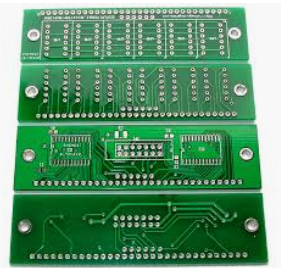
They are chips that control that are controllers that control the relay and other functions, obviously for air conditioning. But as you can see over here, there are no components. That means this will be a one-sided board now. If that’s not confusing enough to a beginner, let’s try to find where there is a connection and where there isn’t a connection; that’s the first part of the Printed Circuit Board.

That Impedance will be tested at this stage using a bespoke impedance coupon generated at the CA m stage and placed on each production Panel. The operator uses the polar CITS eight 0s TDR machine to verify the Impedance. The Printed Circuit boards are then visually inspected under magnification to check for the correct level of artistry as detailed in the customer specification. Finally, all the dimensions and fire sizes are measured on the CMM or the coordinate measuring machine the results are automatically added to the customers. The product’s first article inspection report is now packed in line with the customer’s requirements in protective packaging and moisture barrier bags, along with a humidity card.
The R&D department developed new processes in line with the needs of Merlin’s technology roadmap and fine-tuned them. The current processes to ensure they are running effectively and efficiently; understanding of the PCB production process wall footage was filmed at Merlin circuit technology in Dee-side North Wales; find us at wwlp.com. One of these is indicated in this One. So these two are referring to the ones of this now for continuity to ensure everything is connected correctly.
The function of Printed Circuit Board :
If you see you have this One over here. There should be a beep on continuity, but that must replace the battery on the meter; this is the most straightforward function. So when you do this a little hard to see the meter to include everything, but you can see it goes down pretty much to zero ohms. That is ohms, so anything that has a low value, you’ll get ohms zero ohms close to it, any Printed Circuit Board connection. A good connection should measure in that range, so let’s go over Here. Let’s go over the first one; this is where it’s supposed to be; how do they know there is a connection look at the meter point zero; that’s a good connection.
Let’s say they need clarification on this one; how do they know this is connected to point zero zero zero? They know there’s a connection from here to here. So they know these two points are good; that’s how you keep going from one end to the other across each terminal. Remember, when you go and troubleshoot board modules, you will not have a schematic; the dealership will not give you any schematic Nothing because nobody’s going to go component level on these modules.
Nowadays, it’s just too time-consuming and not cost-effective; you’re not going to pay money on the bench to troubleshoot these Things. But you are just teaching yourself these things because there were comments about these things, so which one is this one they said this corresponds to this One. Let’s say you want to see if this is connected to this point you see over here is connected to this One.